Making a Better Corkscrew
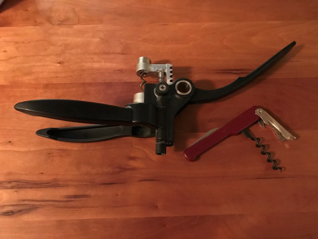
This case study exists to make one idea concrete: with a rolling interface, the designer specifies the motion and the mechanism delivers it. A corkscrew is a good vehicle because everyone has felt the problem in their hand.
Consider the two common corkscrews pictured. The red one is a four-bar linkage (the bottle is the fourth bar), and its mechanical advantage does exactly what you don't want: low at the start, when the cork is stuck fast and the force is highest, then high at the finish, when little force is needed — which is also why it often runs out of throw before the cork is out. The black one, a rack-and-pinion, is better: constant mechanical advantage. But constant still isn't right, it's just not wrong — and it tends to need lubrication to feel acceptable.
The mechanical advantage should follow the force.
To design that corkscrew, you need the force profile of cork removal. It has not been measured, so for this study we assume the force at the start is three times the force at the end — meaning the mechanical advantage should be three times higher at the bottom of the stroke than at the top. With a rolling interface, that ratio-versus-position curve is simply part of the motion specification; the raceway shapes are computed to roll it.
There are many ways to lay out the design. In this one, the lever arm translates vertically at half the speed of the worm; it could instead have purely rotated, or moved with the worm. The specification is the designer's choice — that is the point.
The outcome to look for in the animation: the worm moves three times faster at the top of the stroke than at the bottom, giving the three-to-one change in mechanical advantage that matches the assumed change in force. The motion was written down first; the rolling surfaces were solved to produce it.
Manufacturing
The parts in this system could be made from standard shapes, plates, and dowels, with molded plastic parts forming the rolling surfaces and retainers — likely cheaper than machining them, and with rolling contact throughout, no lubrication would be needed. A molded version would also give the mechanism a notably smooth feel. These are design expectations; like every figure in this study, they are stated ahead of hardware.