The Rolling Interface
Until now, rolling contact has been confined to bearings — round and linear. Bearings are the most efficient and longest-lived interface in machinery, and also the least capable: they support motion, but they cannot shape it. The rolling interface changes that.
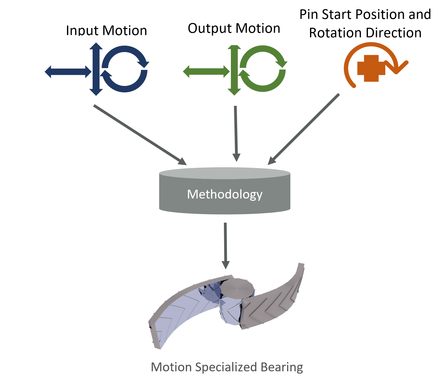
The whole idea in one sentence: a pin rolling between two precisely shaped raceways, guided by a tongue-and-groove retainer at the edges. You specify the motion of two components — positions and rotations, as continuous curves — and the method generates the pair of raceway shapes that deliver that motion through pure rolling. The pin stays in constant contact with both raceways through the full range of motion, it rolls without sliding, and the contact points on the pin oppose each other so the system cannot jam.
The chevron features at the edges are the retainers: a tongue on the pin riding in a groove along the raceway. The retainer guides the pin — in normal operation it is idle. Power is transmitted through the raceway surfaces (blue); the retainer carries no load and drives nothing. Without it, a pin could work its way out of position under transient clearance or disturbance; with it, the pin is positioned kinematically, without adding a sliding element.
The example above was designed as a learning aid: the lower-right component translates smoothly left to right while the upper-left component moves so that the overall mechanical advantage varies continuously from 4:1 through 1:4 — watch it move slowly at the bottom of its stroke and quickly at the top. The motion was specified first; the surfaces were computed to roll it.
Far more complex systems are possible. Rolling interfaces close into loops — the speed reducers and the cycle devices — and run open, in back-and-forth mechanisms. The same capability underlies every case study on this site.
Why this is new
A bearing achieves pure rolling because its geometry never changes: a round raceway, a straight roller, one motion. The moment you ask rolling to produce a chosen motion, the curvature must vary continuously along the path — and a shape like that has no textbook formula. It must be solved numerically, for each design.
The solution runs in two passes in our custom application. The first pass estimates the pin path and raceway surfaces from the motion specification. The second pass refines them: it checks the rolling condition and the opposing contact angles at every interval, adjusts the pin path until the pin rolls without sliding, and resolves the remaining boundary conditions — for a looped device, the criteria that make the pattern repeat exactly.
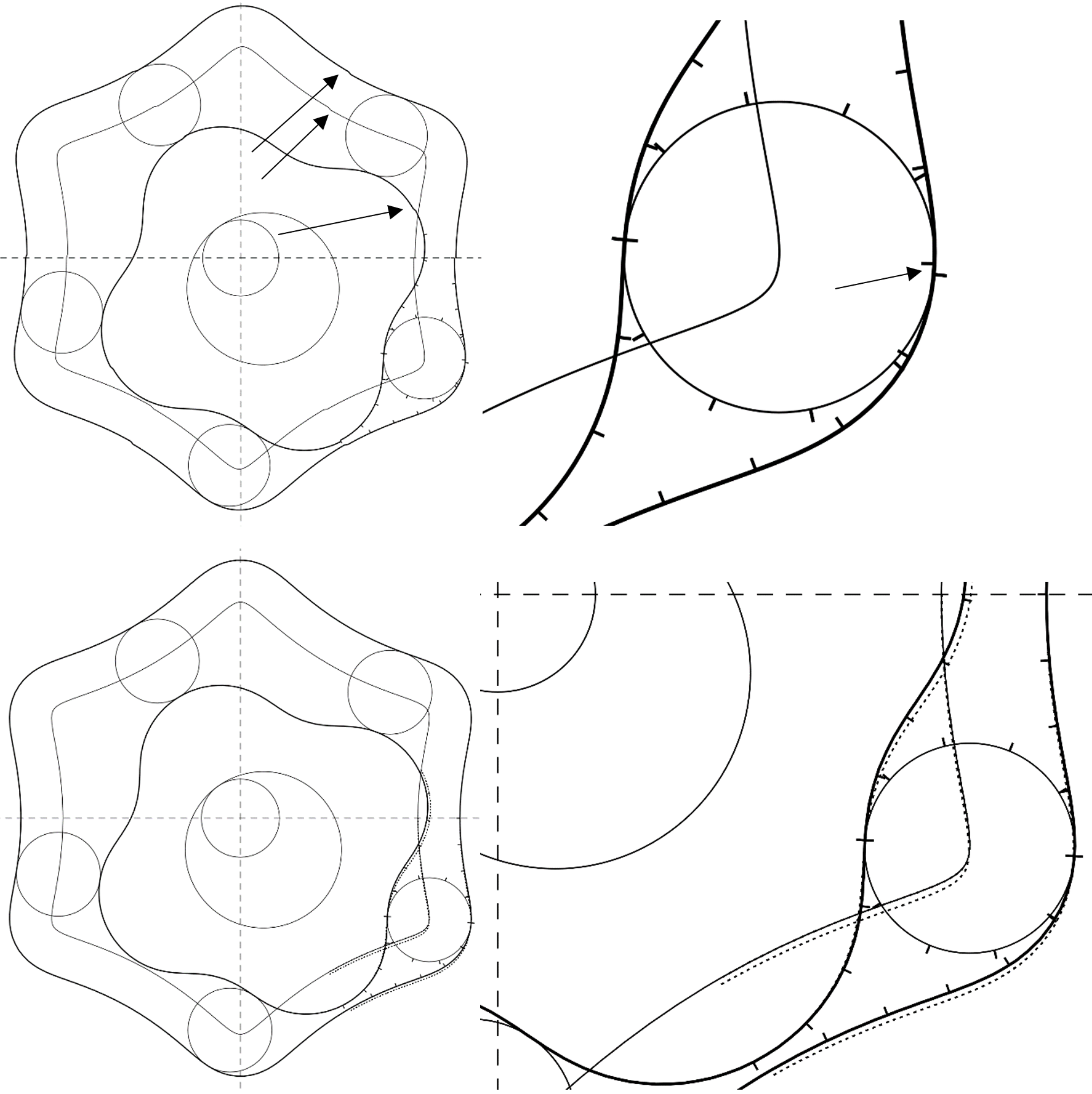
The comparison below shows why the second pass matters. In the first-pass result (top), the repeating-pattern conditions are not yet met and the close-up shows the retainer features misaligned — misalignment there would drag the pin. After the second pass (bottom), the boundary conditions are met, the contour between lobes is smooth, and the retainers align.
That numeric solution — shaped raceways that roll a specified motion — is the subject of our granted US patents. It is why this capability exists now, and why it did not before.
Where things stand: two US patents granted, one pending. A 3D-printed reducer assembles and turns under hand input, which demonstrates the kinematics — not the efficiency. Instrumented efficiency and wear testing is the next phase.
To see the capability applied to thermodynamic machinery, read the compressor case study and the engine case study.
Case Studies
Robotic Walking
A leg joint that keeps the body level through the stride — walking about as efficient as rolling.
Learn More →