Speed Reducers
Our first product line, and the clearest statement of what rolling interfaces are for. The target is the efficiency of a bearing with the function of a gearbox. That is a design target, pending instrumented validation — and even landing near it would change how machines are designed. The reducer mechanism is the subject of granted patent US 12,398,784.
Machines in this family date to 1928 and their descendants are commercially mature. In every one of them, the pins both roll and slide against the raceway — and sliding is where efficiency and service life go. Our raceways are shaped so the pins roll without sliding. Friction is also the engine of wear, so bearing-like durability is the natural expectation — intuition and fact are different things, and testing is the next phase.
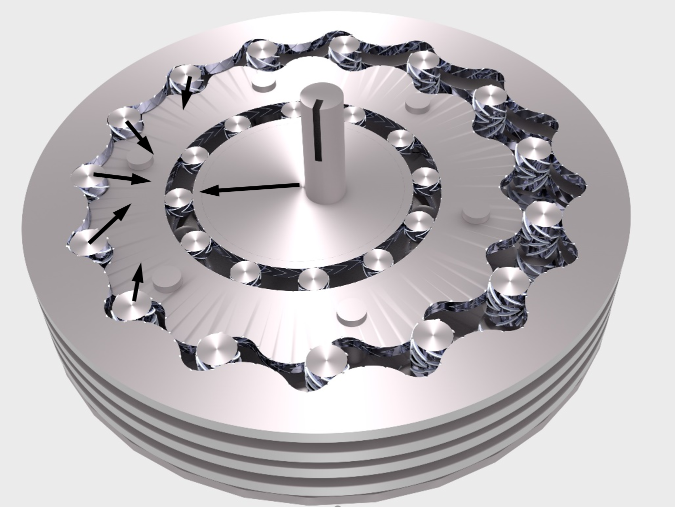
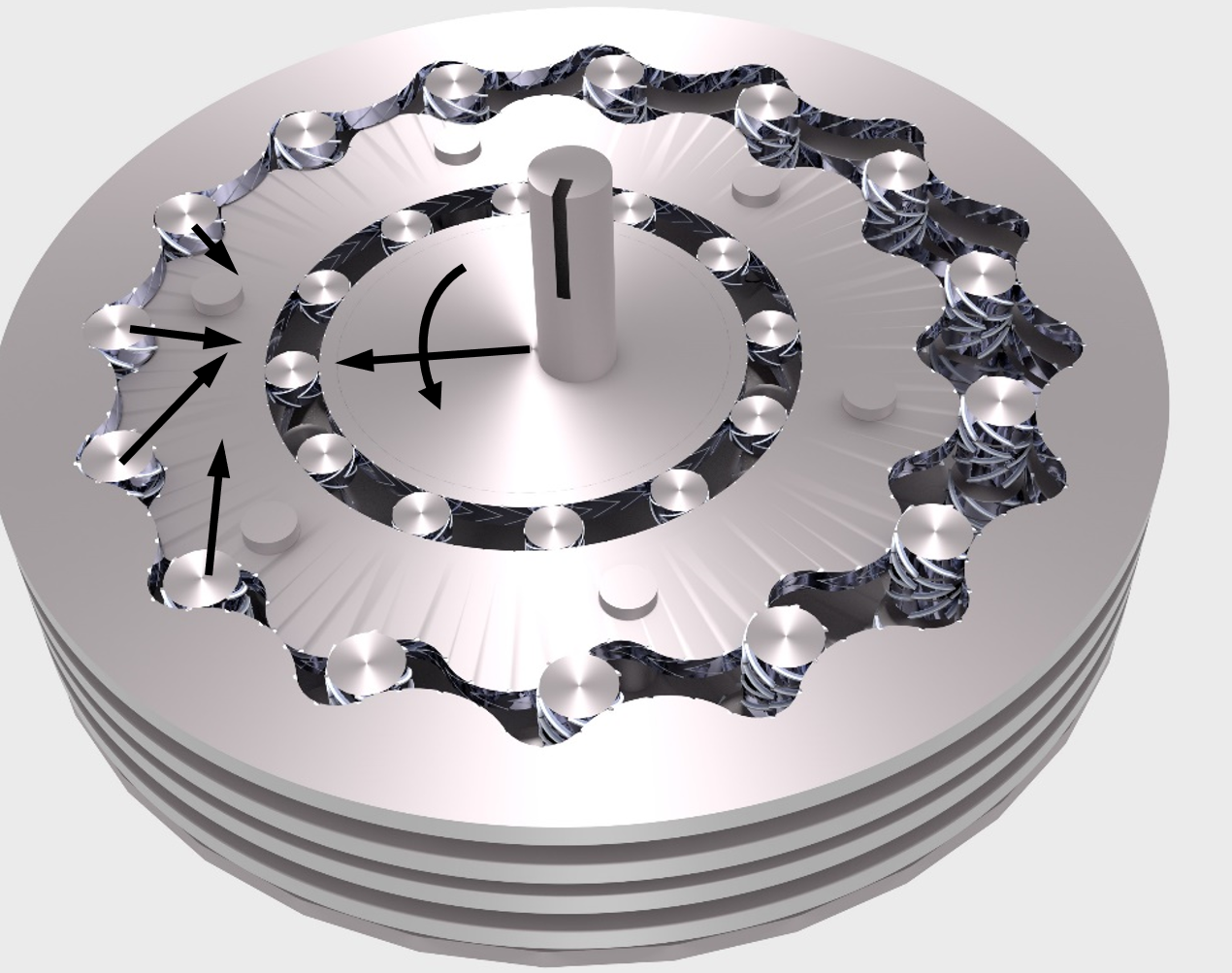
Shown is a 105:1 reducer. The ratio is set by the difference in pin count between the front and the back sets of a single unit — here 14 and 15 pins. There are no stacked gear sets, which matters because in a conventional drivetrain each added mesh charges its own toll: efficiency starts to sag past roughly 3:1 and falls off sharply past about 10:1, so designers stack stages and pay at every one. Take the sliding out and high ratio stops being a compromise. The honest question — the one our test campaign exists to answer — is what a single-unit, high-ratio reduction actually costs in efficiency.
The reducer is designed for:
- Low energy loss — the load path is rolling contact, the same regime as a bearing.
- Smooth, proportional input-to-output motion.
- High torque shared across multiple pins in simultaneous contact.
- Zero backlash by design — a preload takes up the play (explained below).
- Durability — with sliding removed, wear should follow a bearing's pattern; to be proven in test.
- Scalability across sizes and ratios.
Backlash, taken up by design
Systems built from bearings and pins normally carry a small amount of play — backlash. In robotics that play becomes position uncertainty multiplied by the length of the arm. In this reducer, an eccentric preload pushes into the pin sets: multiple pins make contact and support the rotor from opposing directions, so as torque rises the force redistributes among pins without ever passing through loose travel. This is a design feature of the mechanism, to be characterized in hardware like every other figure on this page.
A wide range of ratios — in one unit
Because the ratio comes from the pin-count difference, a broad range is available without changing the architecture. Designs from 10:1 to 253:1 have been simulated. Commonly modeled ratios include:
- 105:1
- 91:1
- 78:1
- 66:1
- 45:1
- 36:1
- 28:1
- 21:1
- 15:1
- 10:1
Other ratios follow from the same method on request.
Example reducers:
105:1
66:1
28:1
10:1
Where things stand: two US patents granted, one pending. A 3D-printed reducer assembles and turns under hand input — kinematics demonstrated, not efficiency. Instrumented efficiency and wear measurement against a geared reduction of equal ratio is the next phase, and the phase we are seeking partners for.